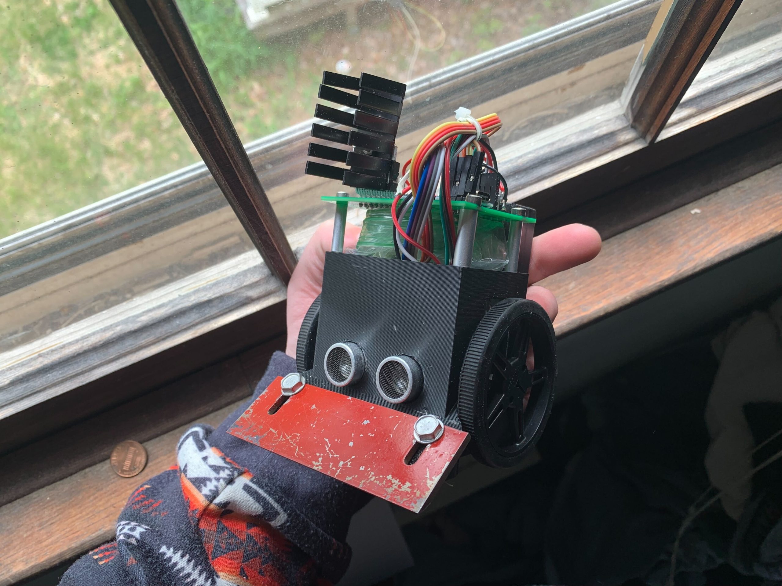
A sumo robot is a robot that is meant to combat other sumobots without destroying them. They are pushers not fighters. They push each other out of a ring and the last robot in the ring wins. A robot is defined as out of the ring if a wheel or track is touching the ground. More information on the rules here. http://robogames.net/rules/all-sumo.php
I was following the mini division of sumo robot rules since that is what we are going to be following for makeit fest. More information on makeit fest here. https://makeitfest.com/
This is a video I made featuring my sumo bot against a zumo. Wins 9 times out of 10 against it.
Now to answer the elephant in the room, how do I build this robot. Well first you need the blueprints off of cults which you can download here. https://cults3d.com/en/3d-model/gadget/sumobot-2025-and-sumofest-board-v1
Now next you must 3D print and build the pcb inside the zip file. The pcb is super easy to make. Here is how you make it.
- You need the following components. An 7805 regulator TT0-220 style, an l298n motor driver, heat sink for the l298n motor driver, short m3 bolt to connect the heat sink to the l298n motor driver, arduino nano v3, and male pin headers.
- Solder the 7805 regulator to u1. Make sure it is connected the right way. Should be labeled on the pcb where it goes and how it should be connected.
- Solder the nano to A1. Should be labeled on the pcb how it goes on the board.
- Solder the l298n board to the board. Should be labeled how it goes on the board.
- Put the heatsink on the l298n driver with the m3 bolt & nut.
- Solder the rest of the pin headers with the 2.5mm male pin headers.
The board looks like this unsoldered by the way.

Now 3D print the body and the motor mounts. You need two motor mounts, and one body. The motors can be bought here. https://www.servocity.com/premium-n20-gear-motors/
The wheels can be bought here. https://www.servocity.com/60mm-black-robot-wheels-3mm-bore/
And lastly the sensors for seeing the sumo ring can be bought here. You need two of these sensors. https://www.pololu.com/product/4201
To assembly the robot you need the following.
- Sumofest board v1
- 4 * 25mm standoffs
- m3 and m4 hardware set
- 3d printed parts as listed above
- A wedge to by cut out of acrylic or metal. Metal is perfered. DXF file for wedge is in the cult3d zip file as listed above.
- HCSR04 sensor
- Wheels as listed above: https://www.servocity.com/60mm-black-robot-wheels-3mm-bore/
- IR line follower sensors as listed above: https://www.pololu.com/product/4201
- Hot glue and gun
- Motors: https://www.servocity.com/premium-n20-gear-motors/
- 18650 battery holders and battery. Battery holders can be bought here. https://www.amazon.com/dp/B07CWK79KG?ref_=ppx_hzsearch_conn_dt_b_fed_asin_title_1
To assembly the robot you must do the following.
- Solder pig tails coming out of the ir sensors. Do not need to solder a wire the control pin on the ir sensors since they aren’t used.
- Hotglue the ir sensors to the bottom of the robot. There are two squares that are designed to hold the ir sensors in place indented to the bottom of the robot.
- Attach the wedge to the robot by inkjet printing out the dxf file on a printer and cutting it out manually with a bandsaw or use a water jet like I did out of steel or aluminum. Then use a belt sander to sharpen the tip of the wedge. The wedge attaches to the robot with m4 bolts.
- Let the wedge extend out of the robot by 4 or 5 mm.
- After you solder pig tails on the motors, put them in the motor mount, and screw the motor mounts in with m3 bolts from behind the robot. There should be indents of where the head of the bolts go so they aren’t sticking out.
- Screw in the battery holder to the back of the robot using beveled m3 hardware so they don’t stick out too much in the battery holder. There should be four holes on the back of the robot near where you just screwed in the screws to hold the motors where the battery holder goes.
- Next use 4 standoffs to mount the pcb to the top of the robot. Use 4 30mm bolts to the 25mm standoffs.
- Next follow the pinout listed below.
B: Battery voltage in pin.
G: Ground
A0 & A1: These pins connect to the signal on the ir sensors.
Sonars: The middle pins on j4 and j3 are echo or trig pins depending on how you program your robot. The other pins on the ends of that connector are 5v or ground respectively to the sonars.
Nano: The pins on the nano connected to the motor driver, sonars, and ir sensors are labeled on the board.
You may need to solder the wires directly to the pin headers to get it to work. Feel free to use hotglue and heatshrink as a insulator.
The robot has some room on the inside of it you can stick bbs in a bag and tie the bag shut. That is too push the weight of the robot while still being under 500 grams.
Thanks!
Leave a Reply